Progress Log
Week 14 - Fully Integrated Solace Prototype
Week 8 - Communication and Connection:
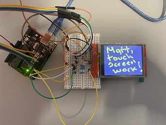
This week the group focused efforts on microprocessor communications and data display. The Bluetooth communications test has shown results of successfully transmitting and receiving data. The team will next test the transmission and reception of data from one microcontroller to another. Furthermore, the touch-screen display is also working in the system. Last week we were able to troubleshoot the motor and diagnosed the issue of the IC driver overheating. The root of this issue was the limited amount of current the driver was rated for compared to the continuous high current draw of the stepper motor. Furthermore, the motor is ready to be mounted to the frame once the axle and flange are fitted. Following this weeks progress presentation with Professor Notash, the group has set a a time to meet up to test the Bluetooth communications between both microprocessors and to prioritize system integration.

Week 10 - Implementation:
Week 9 - Integration and Interconnectivity:
Much progress has been made in the past week. The group met up to and successfully diagnosed the issues with the Bluetooth communications and after corrections, we were able to drive a motor wirelessly, controlling speed and direction with a potentiometer. Furthermore, the issues with the anemometer were also fixed, and now we are able to see the correct output for windspeed in the serial monitor of the Arduino IDE. With the auxiliary sensors now outputting the information, the challenge is displaying that information in an easily readable and intuitive user interface. This leads in to the LCD panel which has been correctly configured to work with the system and now offers touch screen capabilities. The team is meeting today to ensure that the data being read by the slave microcontroller in the weather station can correctly and efficiently transmit that data to the master microcontroller and display that information on the LCD panel. With all sensors correctly wired, communicating, and providing valid data, the team can finalize their positions when mounting them into the weather system casing. During todays group meeting, we will also be further discussing our plans to fully mount and integrate both systems. The team believes we are ready to make the necessary modifications to the framework to house the components to reflect our initial visions of this project.


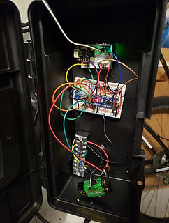
This week, the group made much progress in terms of implementation. The framework for both the internal and external systems has been improved upon to provide additional housing for the components. The framework for the internal system now has an accessible panel for housing the microcontroller, motor, battery pack, wiring, etc. The motor has been mounted to the frame and the blinds and roller are ready to be implemented on the arrival of the axle coupler for the motor. The framework for the external system now accompanies housing for all of the auxiliary sensors and wiring for the solar panel, anemometer, and rain sensor to exist outside of the frame.
Furthermore, the motor is now running optimally with no overheating issues thanks to troubleshooting the low amperage rating of the initial driver. The new driver has a much higher amperage per coil rating, allowing extended use of the motor with little to no heat emitted. The motor is programmed to run automatically or to wait for the signal from a pushbutton for manual operation. The motor has been mounted to the framework with the wiring leading to the back panel for accessibility and discretion.
Lastly, the Bluetooth communications has been expanded upon, however, the team is encountering an issue when trying to relay sensory data from one module to the other. The team has been advised to reach out to a few members of faculty while also utilizing other resources found in our research to successfully diagnose and correct the issue. Once the issue is corrected, the team can transition into relaying the data onto the LCD screen for the user interface.
Week 12 - Integration & Testing


Week 11 - Axle & Data Display:
This week, the group improved upon the framework for each system as we approach full system integration. The axle, flange, and motor have been successfully affixed to one another so that the motor can drive axle to wind or unwind the curtains. The curtains themselves have been sewn in order to slide the axle or weight bar on and off the design. The group needs to ensure that the axle is level across the frame and evenly spaced before we can conduct further tests.
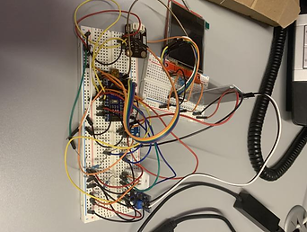
Work is continually being done to improve the frame and the user interface. Bluetooth communications are successful for sending the data of multiple sensors from slave to master. We are able to display that data on the LCD panel, however, we are working on improving the accessibility and readability of the data. The data that is being displayed is including excessive characters and displaying the data awkwardly on the available lines. The data is also being displayed too fast and needs to be formatted to be more user-friendly. Soon, the framework will have additions to accompany the LCD panel and a station for charging mobile devices.

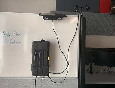
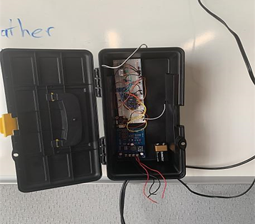
The team integrated the hardware to the framework for both halves of the design. The weather station was weather-proofed and tested for a tight water seal in order to protect the electronics within. Using a local weather site, the sensors were tested for reliability, accuracy, and consistency. The tests were taken several times a day over the span of a week and yielded successful results. Following suggestion from Prof. Notash, the frame of the weather station was reduced in size to be more compact in design. The Bluetooth was tested for transmission reliability up to a distance of 30 feet or 10 meters. The sensory data is successfully being displayed to the serial monitor, however, the data being displayed to the LCD is still experiencing errors. The troubleshooting of this part of the project has attributed the errors to the lack of RAM of the microcontroller powering the LCD. The group will be meeting tomorrow to test the LCD and code with the Arduino Mega2560 which has much more RAM. Furthermore, the blinds system is integrated and only lacking the housing for the LCD and the mobile device charging station. The group is recalibrating and performing tests in order to maximize efficiency and optimal performance for the system operations.
Week 3 - Framework & Testing:
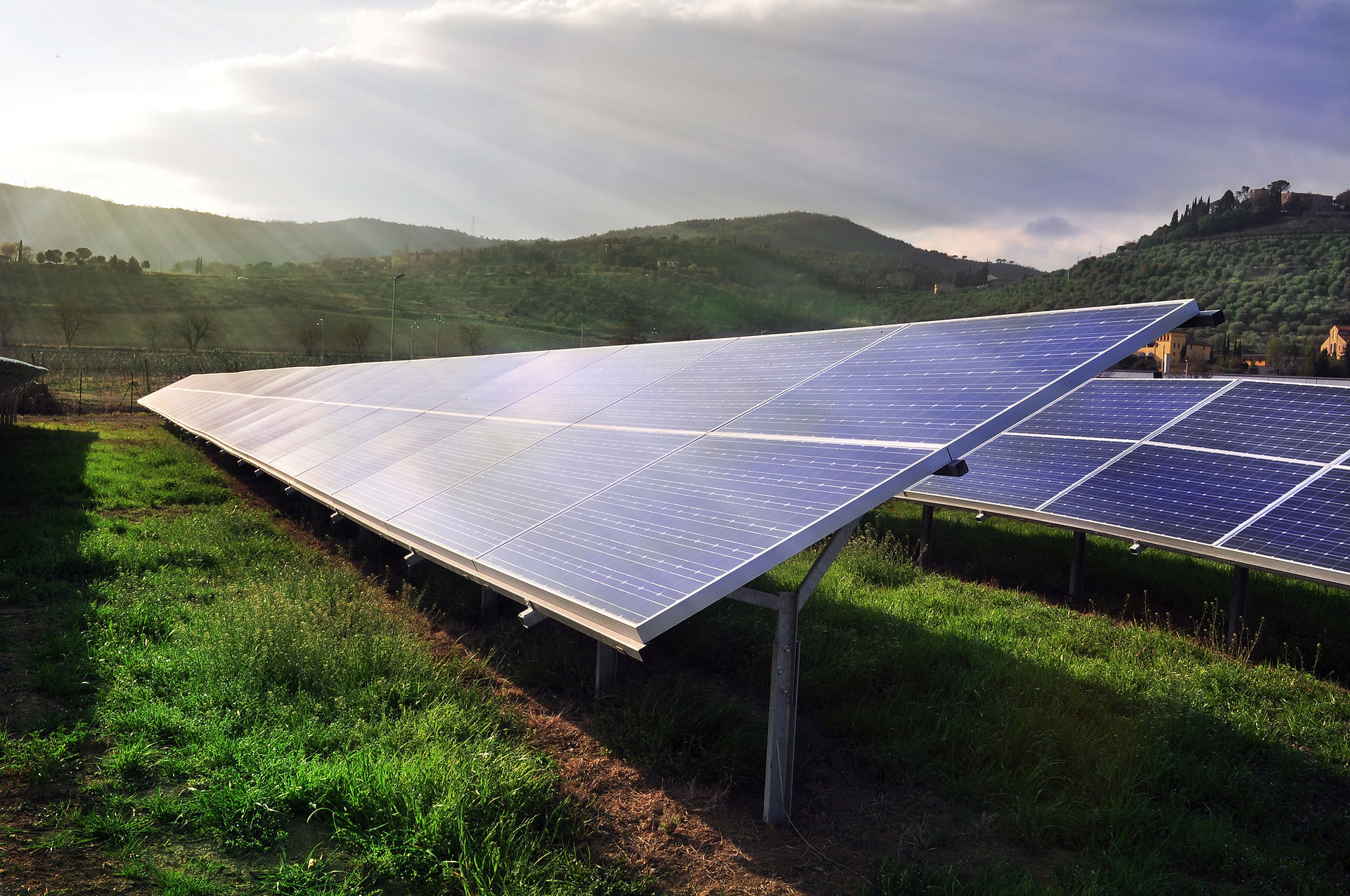
The frame of the project has been designed and the materials were purchased. Construction began over the break and was finished this week. The framework consists of 2-inch by 4-inch wooden support beams held together by L-brackets and wood screws. The dimensions of the frame are 3.5 ft by 2.5 ft to represent a scaled down version of an actual standard residential home-sized window. All components have arrived, however, during the break Matthew & Douglas discovered the need for additional components not previously thought of. These two components are a solar charge controller and a lithium-ion battery bank which are essential components to the function and design of the system. These components act as a voltage regulator between the solar panel and the micro-controller and other components which was thought of and included in our original proposed design. The testing of these components has been somewhat arduous and slow due to shipping time delays impacted from Covid-19 and unfortunately inclement weather. The rainy and cloudy weather of the past week has interfered in our testing and has made it difficult to get accurate sustained readings from the solar panels, charge the battery bank, and implement the solar charge controller into the design. As to stay as closed to our original proposed phase 2 timeline as possible, we have decided to begin developing the software behind the system as we continue to wait for better weather for testing. Meanwhile, the website layout for the project design tab has been overhauled. Many changes were made this week to catch the website back up make all the information current. All of the tabs were redone to reflect the most up-to-date information and some changes spilled over into the proposal tab as well. Some information, understandably, will be the same as the proposal tab until later in the design process when we can update this data.
Week 4 - Coding and Charging:
This week was spent starting the foundations of coding the auxiliary devices in both halves of the system. For the weather station, we are working on developing the code for the the temperature, humidity, rain, and anemometer sensors to measure and relay their data back to the microprocessors. For the blinds system, the code was written for the motor, however we came upon needing an additional IC to have the Arduino microprocessor drive the motor. The IC was ordered and is en route. Once delivered, we will be able to troubleshoot or fine tune the torque, direction, and duration of the motor via code in the system. More importantly, we have reached power distribution continuity between charging the solar panel, using the solar charge controller has a voltage regulator, and having that voltage charge up our Lithium-Ion battery pack. Images and a video showing our progress with this very integral achievement can be found below. The trickle charging of the battery pack is a slow process, however, once the voltage displayed on the charge controller reaches 12.7 volts, it will be fully charged.


Week 5 - Synchronization & Sensors:
This week, the main focus of our efforts lie in writing and troubleshooting the software that will be going into our design. The codes for the Bluetooth, Pressure sensor, temperature sensor, UV sensor, humidity sensor, are fully completed. The code for the anemometer is still a work in progress. Each block of code for the auxiliary sensors has been loaded onto the Arduino Nano microprocessor one at a time in order to be tested. A roadblock was encountered with the Arduino Nano output port. When trying to open the Arduino serial monitor (from the sketch application), an "unavailable port COM4 connection failure " message is observed. Currently, we are not sure if the issue results from the PC port, the Arduino Nano port, or if it is a connectivity issue. Therefore, we can not say with certainty that the sensors are reading external weather conditions with accuracy. Additionally, we received the chip to drive the stepper motor and have set up a time to meet up in order to test the chip and the code for the motor. Furthermore, this meet-up will provide us an opportunity to survey where we are at with our design and where out focus should be with our components and software moving forward. Once we can verify the components are working as intended and the devices are well synchronized, we can incorporate them into the framework in a more semi-permanent fashion.
Week 6 - Testing & Troubleshooting:
This week, the team was able to meet up to share the progress we've been making and bring all the components together in the same room. This helped to visualize our goals and what the final product may look like. This meeting also provided the group with the opportunity to get some much needed testing done, especially with the motor. After a few quick troubleshooting attempts, the code compiled and was uploaded to the board, the circuit was wired, and power was provided with a flip of the switch. Once the lithium-ion battery pack provided the power for the motor, it began spinning clockwise and counter clockwise as the code written had instructed. This was a big success but not without discovering a slight setback. The IC used to drive the motor heats up extremely quick, a downside that we can not overlook in our final design. After some more troubleshooting and research, we determined the best route forward was to bring in a more up-to-date IC that can drive larger loads more efficiently.
Furthermore, each of the elements that composed the weather station was wired and connected to the Arduino for testing. Through the Arduino sketch monitor window, the elements provided an observable output. Meaning, the microcontroller processed the uploaded code, and the elements responded by providing an output. Debugging will continue to test the accuracy reading of each element. However, the team encountered a roadblock with the anemometer. We will continue to troubleshoot and research a solution. Simultaneously, the housing, wiring, and power for the weather station are on the way.
Lastly, the ability for the design to power and charge cell phones was tested and produced successful results. Our initial findings yield that the design will be able to charge a single cellular device from 0% to 100% in about 3 hours, even while simultaneously driving the motor.

With the recent unforeseen additions to the design, the group has decided to update the expense budget and system block diagram so that our documentation is up to date for viewers of the site and for ourselves when it comes time to finish our report. On the technical side, we are analyzing our motor circuit to deduce why we are still experiencing rapid heat build-up in the new IC. We went as far as to order a new, bigger breadboard and new jumper wires in case we had an issue with the existing board or wires. Furthermore, the wiring for the external system continues as the frame comes together. The anemometer is still being worked on and will be the last sensor incorporated into the final external system. Currently Bluetooth communications between microcontrollers is being worked out as that is integral to the overall configuration of the working system. Lastly, the LCD panel that will display the information read out from the primary microcontroller is also under development.
Week 1 - Components & Circuits:
Week 2 - Framework & Calibrations:
The solar panels arrived so that we could provide power to our components. The group tested the panels and measured the output. Some of the components were also tested and the code re-calibrated to accompany the design of our project. Some of the documentation was brought up to date and the website updated as well to reflect the most recent purchases and additions to the project. The tests performed yielded good results, however, the team realized that there are other components missing from the initial proposal of the design. A voltage regulator in the form of the solar-charge controller was required in order to regulate the voltage being used to trickle charge the battery pack.
The team researched and purchased the last of the components and began assembling the circuity required for the components that had arrived. The framework was discussed and worked on for the internal blinds system. Some brackets were drilled into place and the team discussed where components would go and what the ultimate look of the design should resemble given the components that were in-hand. Some basic circuitry was worked on this week so that as more parts begin to arrive, we can get start performing tests on the components for functionality.
Week 7 - Testing & Troubleshooting Cont'd:
Week 13 - User Interface, Integration, & Testing
This week, the team focused intently on full integration and testing combined with the user-interface. The mobile app is designed to operate via a Bluetooth connection. Once connection is established, the application will allow the user to manually control the motor operating the blinds. The display will acknowledge whether or not the user has successfully connected to the app, and will provide an option to draw or open the blinds. Furthermore, on another screen, the user will be able to read the weather data straight from the weather station, supplying the user with the sensory data that has been collected. On the LCD panel, a similar configuration is used. The user will be able to select the weather information they want to access. Once the user has made a selection, the user is brought to a new screen that will display the chosen information. On each screen, the user is also provided with a "go back" button to return to the previous screen. The team still has further testing to do in order to ensure the full accuracy and intended operation of the user-interface. Another notable piece of progress to log is the framework is outfitted with a docking station, allowing the user to charge their mobile devices for convenience.

The team worked to refine the software and the hardware after last weeks testing trials and redesigned the GUI of the user-interface after last weeks meeting with Prof. Notash. After much trial and error, the fully integrated prototype was ready for testing once again. This time around, the prototype passed all tests with little to no errors in performance. The LCD display updates in real-time, obtaining live updates from the weather station. These same data readings and updates can be remotely accessed on the mobile app which has finished development. The mobile app can also remotely control the motor that powers the blinds from a distance of up to 10 meters. The motor, weather station, and mobile application were extensively tested over a series of five separate trials to ensure the validity and the reliability. In it's current state, the Solace prototype meets all of the success criteria outlined during the proposal phase of the project design.
Week 15 - The Report
This week the team's sole focus was on updating all of the pertinent documentation and combining all of the data into one cohesive and professional report. The appended budget, power budget, actual timeline, system block diagram, and more were all updated on the report as well as the Solace webpage. The team elaborated in extensive detail the inner workings and technical data and schematics that went into making the Solace design. The team also detailed the steps from system proposal of two separate halves into one fully functioning integrated system. The report includes the technical details of the design including the joining of both systems, the results of the prototype testing trials, and the fully commented code. The non-technical details including the appended budget and socio-economic aspects of the design are also detailed. The report concludes with the teams suggestions for future work.